
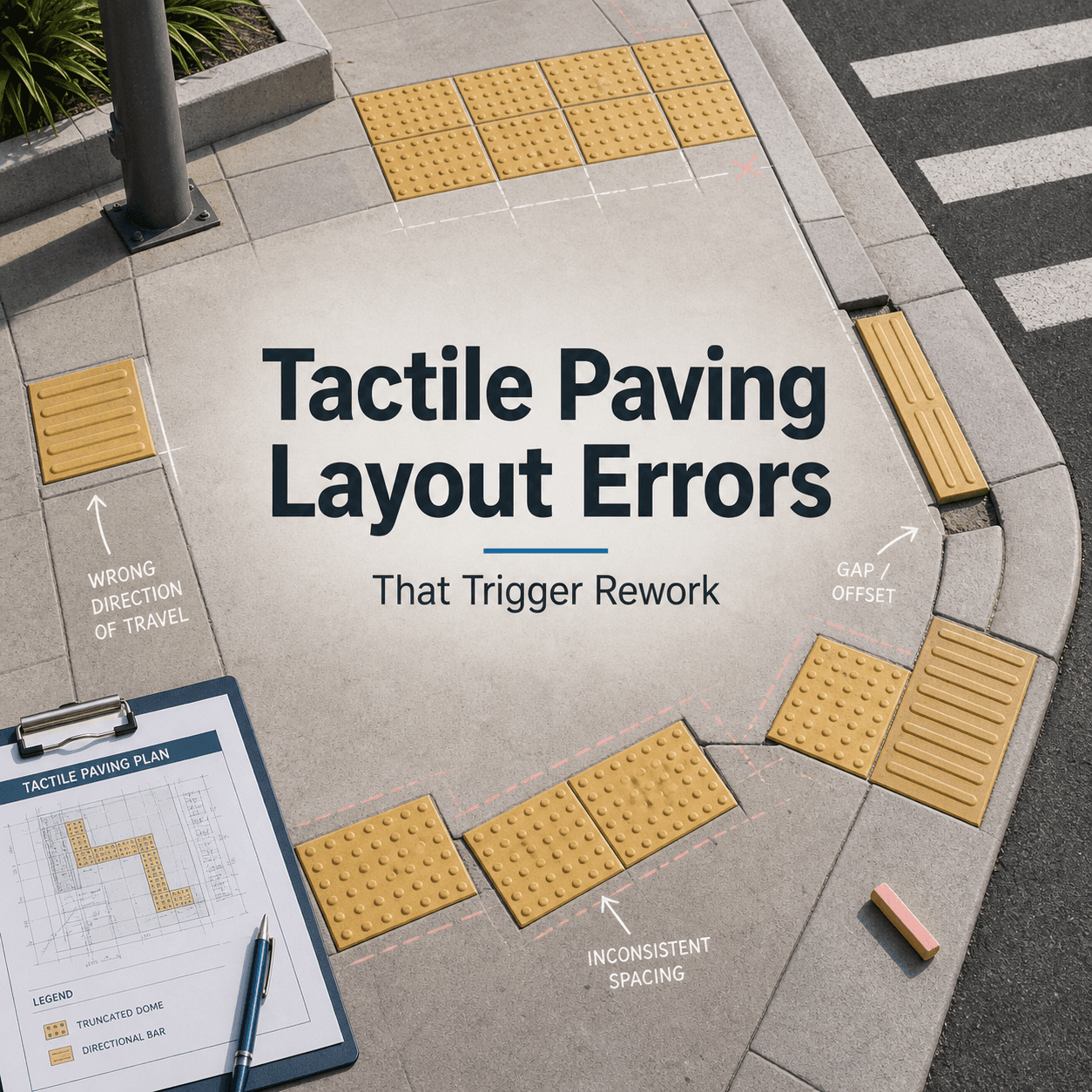
O pavimento tátil é uma daquelas coisas que parecem simples até você ter que instalá-lo de fato em um local real.
Algumas fileiras de pontos e algumas barras é tudo o que é preciso — e pronto. Só que raramente as coisas correm tão bem assim.
O retrabalho que observo nas instalações de ladrilhos táteis não se deve ao fato de os ladrilhos serem ‘ruins’. Isso ocorre porque o layout ficou ligeiramente desalinhado, o padrão foi utilizado na posição errada, o instalador seguiu à risca as plantas arquitetônicas sem levar em conta as condições reais do local, ou a equipe tratou as placas táteis como se fossem ladrilhos comuns. Mas elas não são.
Este artigo é, essencialmente, uma lista de verificação dos erros de layout que levam a retrabalho, reprovações em inspeções, e-mails irritados de clientes e aquela situação desagradável em que alguém diz: “Temos que refazer isso.”
Por que a reparação do pavimento tátil é tão comum
Um caminho tátil constitui um sistema que fornece informações tanto aos usuários de bengala quanto às pessoas com baixa visão; se o sistema for inconsistente, estiver desalinhado ou for confuso, isso não se trata apenas de um defeito estético, mas passa a ser uma questão de segurança e conformidade.
Por isso, os inspetores e consultores costumam ser rigorosos em relação a:
- Seleção correta do padrão (aviso x orientação)
- Posicionamento correto em relação aos riscos e pontos de decisão
- Alinhamento e direcionalidade consistentes
- Contraste, legibilidade e continuidade
- Distâncias livres em relação a obstruções e portas
- Os detalhes da transição, porque é aí que as coisas dão errado
A parte mais cara não é o azulejo. É a mão de obra, a demolição, o descarte e o impacto no cronograma. Se você conseguir evitar erros de layout antes de abrir o adesivo, economizará bastante.
Por exemplo, se você souber quanto custa o pavimento tátil, poderá gerenciar melhor as despesas durante a instalação. Também é importante ter em mente que, ao instalar pavimento tátil para pessoas cegas, é preciso levar em conta certas considerações para garantir a segurança e a acessibilidade. Em lugares como as Filipinas, essas instalações estão se tornando mais comuns devido à crescente conscientização sobre a acessibilidade.
Erro 1: Usar o tipo tátil errado no lugar errado (pontos x barras)
Essa é, muito provavelmente, a principal razão para a remoção total.
- Indicadores táteis de aviso (geralmente compostos por cúpulas truncadas e um (padrão de pontos) são usados para alertar as pessoas sobre riscos e mudanças; exemplos incluem as bordas das plataformas, as rampas nos meios-fios, degraus e pontos de travessia.
- A orientação tátil (geralmente na forma de faixas direcionais) é utilizada para orientar o movimento ao longo de um trajeto seguro, especialmente em áreas onde não há uma borda natural para servir de referência.
Onde está o problema:
- Foram instalados pontos ao longo do corredor para servir de caminho.
- Barras instaladas no topo das escadas porque alguém achou que “direcional” significava “na direção das escadas”.
- Padrões misturados em um único local, sem uma lógica clara.
Se for instalado o tipo incorreto, geralmente não é possível ‘corrigi-lo’, uma vez que toda a mensagem fica alterada. É por isso que isso é classificado como retrabalho e não como um defeito menor.
Erro 2: Barras direcionais giradas ou distorcidas (o trajeto aponta na direção errada)
O tátil direcional só funciona se realmente indicar a direção para onde você pretende ir.
Erros comuns de layout:
- As barras foram giradas em 90 graus no patamar devido ao módulo de azulejos.
- As barras estavam se desviando gradualmente da linha prevista, uma vez que a equipe seguiu as linhas de argamassa em vez do eixo prescrito.
- Uma linha perfeitamente reta, embora seja reta, leva a um destino errado.
Isso ocorre quando o arquiteto define o trajeto na vista em planta, mas, na realidade, a linha desejada é diferente; o instalador precisa então tomar uma decisão, e geralmente é essa decisão que é identificada.
Prevenção prática: marque a direção tátil com um fio de giz preso a pontos de referência reais, e não a ladrilhos próximos que também possam se deslocar.
Erro 3: Falta de consistência no planejamento do deslocamento e do módulo, fazendo com que o padrão fique mal alinhado nas bordas
As placas táteis são modulares, mas o piso ao redor delas não precisa ser; e se você não planejar o módulo desde o início, as placas táteis podem acabar ficando assim:
- Lâminas finas nas bordas
- Meias peças em pontos de decisão
- Campos de pontos truncados que parecem um erro
- Barras direcionais que terminam na nervura central
Os inspetores e os clientes detestam isso porque passa uma impressão de descuido e pode gerar sinais inconsistentes.
É importante, nesse caso, escolher um fabricante que ofereça dimensionamento confiável e resultados consistentes entre os lotes, embora o layout ainda precise ser planejado. Quando se utilizam tamanhos padrão, tais como Ladrilhos táteis de 300 × 300 mm ou 200 × 200 mm, é preciso projetar a grade ao redor deles, e não considerá-los como algo a ser acrescentado no final.
(O site Design-Ceramics.com lista as opções táteis por tamanho, o que facilita o planejamento inicial dos módulos, já que você pode escolher um formato que realmente se adapte ao espaço, em vez de ter que fazer cortes posteriormente.)
Erro 4: Distância inadequada em relação aos obstáculos (muito perto ou muito longe)
Existem falhas comuns em muitas diretrizes, mas o que importa é o seguinte: o campo tátil deve estar na relação correta com o risco sobre o qual está alertando.
Problemas típicos relacionados a “distância excessiva”:
- As placas de sinalização são instaladas bem na borda do meio-fio, de modo que as saliências se projetem parcialmente para dentro do declive; caso contrário, haveria risco de tropeço.
- Foi instalado bem encostado no degrau, de modo que a área do primeiro degrau ficou cheia de coisas.
- Nas bordas da plataforma, instalados tão próximos uns dos outros que o campo não fica onde se esperava.
Problemas típicos do tipo “exagero”:
- O campo de aviso está instalado tão atrás que já não oferece um aviso a tempo.
- Nas travessias, instaladas afastadas da rampa de acesso à calçada, de modo que o usuário encontre primeiro a inclinação e, em seguida, o sinal de alerta.
Trata-se de erros de layout, e não de defeitos nas placas, e isso muitas vezes leva à remoção, pois deslocar o campo em apenas 50 a 150 mm significa ter que levantar uma seção inteira.
Erro 5: Quebra da continuidade nos pontos de decisão (o caminho desaparece, recomeça ou se torna ambíguo)
Um percurso tátil não deve parecer um quebra-cabeça.
Os gatilhos de retrabalho aqui incluem:
- As barras direcionais param por 600 mm porque “há um ralo” e, em seguida, retomam o movimento. O usuário percebe isso como uma perda de orientação.
- Dois caminhos em direções opostas se cruzam, e não fica claro qual deles continua.
- O percurso termina em uma parede, um canteiro, uma coluna ou uma porta giratória. O ponto final não corresponde à intenção.
O problema é que as plantas podem parecer boas, mas, assim que os móveis, os postes de delimitação, a sinalização, as grades de fila ou as catracas são instalados, o trajeto fica comprometido.
Se possível, faça um “recorrido tátil” com o coordenador geral e o consultor de acessibilidade antes da instalação definitiva. Literalmente, fique no local onde o azulejo será colocado e pergunte: “Para onde isso te leva?”
Erro 6: Instalação de ladrilhos táteis dentro da área de abertura das portas ou diretamente nos limiares
Esse tipo é extremamente comum em entradas de estabelecimentos comerciais.
Entre os erros estão:
- Foram instalados pontos na área onde a folha da porta se move, causando arranhões, ruídos, desgaste prematuro e uma sensação estranha de irregularidade sob os pés quando se está em pé e puxa a porta.
- Barras direcionais que atravessam diretamente um limiar onde um poço de tapete ou trilho as interrompe.
Se os botões táteis precisarem ficar próximos às portas, o layout deve respeitar:
- Portas giratórias
- Poços de malha
- Trilhos embutidos
- Quedas de drenagem
- Quaisquer perfis antiderrapantes para bordas de degraus
Caso contrário, ocorre um “conflito funcional”, e isso acaba gerando retrabalho, pois não é aceitável deixar a situação assim.
Erro 7: Alinhamento inadequado nas juntas de dilatação, juntas de controle ou entre diferentes substratos
Mesmo que o campo tátil em si esteja configurado corretamente, muitas vezes ele se sobrepõe:
- Juntas de dilatação
- Juntas de controle cortadas com serra
- Transições da laje para a rampa
- Transições para bordas de metal ou pedra
Se o layout tátil ignorar essas junções, duas coisas acontecem:
- O risco de rachaduras aumenta.
- Quebras no alinhamento visual e tátil, especialmente nas barras direcionais.
Então, o cliente diz: “Parece errado”, e o consultor responde: “A leitura está errada”, e tudo precisa ser refeito.
Uma abordagem mais adequada é utilizar as juntas como principais pontos de referência durante a fase de piquetagem. Em alguns casos, o traçado tátil deve ser ligeiramente ajustado para que se alinhe corretamente com a malha de juntas; em outros casos, será necessário introduzir uma interrupção deliberada e reiniciar o detalhe, mas isso deve ser feito de propósito, não por acidente.
Erro 8: O contraste e a orientação foram ignorados; portanto, o elemento tátil “existe”, mas não é legível
Essa é uma armadilha, porque o azulejo pode ser instalado perfeitamente e, mesmo assim, não atender às expectativas.
As falhas de contraste relacionadas ao layout incluem:
- A cor do piso tátil é muito semelhante à do piso ao redor, de modo que o trajeto se perde visualmente.
- Diferentes lotes ou zonas em que a textura tátil muda, prejudicando a uniformidade ao longo de um trajeto extenso.
- Campo de advertência instalado de forma a se misturar com uma linha de sombra ou faixa de contorno, de modo que o limite desapareça.
Isso pode exigir retrabalho quando a especificação exige um determinado contraste visual e a instalação no local não atende a esse requisito. Nem sempre se trata de números exatos no local. Às vezes, é simplesmente óbvio.
Se você estiver escolhendo os ladrilhos táteis com antecedência, peça amostras e observe-as ao lado dos ladrilhos reais do entorno, sob as mesmas condições de iluminação. A Morera Ceramic Tile Company oferece amostras grátis e opções de personalização de cores, o que ajuda bastante aqui, porque você não é obrigado a se contentar com o que estiver disponível localmente naquela semana.
Erro 9: Tamanho incorreto do campo tátil (muito pequeno, muito curto, proporções erradas)
Uma área de aviso muito rasa pode não ter sentido do ponto de vista funcional. Uma faixa direcional muito curta pode causar confusão. E uma área muito grande pode criar desordem e risco de tropeço.
Isso acontece porque:
- A equipe dá uma olhada.
- O desenho mostra um símbolo genérico, não as dimensões.
- O traçado é feito depois que os outros profissionais ocupam o espaço.
Quando um inspetor sinaliza que “o tamanho do campo não está de acordo com as especificações”, isso geralmente significa que é preciso retirar e recolocar. Pois não é possível esticar o material sem alterar a quantidade de ladrilhos e os cortes.
Erro 10: Cortes que prejudicam a geometria tátil (cúpulas cortadas, nervuras seccionadas)
Isso é metade planejamento, metade execução. Mas a causa principal costuma ser o planejamento, porque o módulo não foi planejado.
Se você acabar cortando os azulejos táteis de forma que:
- As cúpulas são cortadas ao meio nas bordas.
- As costelas terminam em fragmentos pontiagudos.
- A borda do campo é irregular, não é um retângulo bem definido.
Parece errado e dá a sensação de estar errado. Além disso, algumas normas e alguns clientes não aceitam domos cortados nas bordas, pois isso altera a sensação tátil e pode criar bordas afiadas.
A solução não é “cortar melhor”. A solução é planejar com antecedência para que você coloque as peças inteiras onde a geometria tátil é importante e, em vez disso, faça os cortes nas peças lisas ao redor.
Os pavimentos cerâmicos táteis de corpo inteiro são duráveis, o que é ótimo, mas não são mágicos. Você ainda não vai querer passar o dia inteiro se arrastando por campos de cúpulas só porque o projeto foi feito às pressas.
Erro 11: Misturar espessuras ou acabamentos de azulejos sem planejar as transições
Se os ladrilhos táteis ficarem salientes ou afundados em relação aos ladrilhos adjacentes, as pessoas percebem. As cadeiras de rodas percebem. As equipes de limpeza percebem.
Isso pode ser causado por:
- Diferenças na espessura dos azulejos entre a área tátil e a área circundante
- Espessura variável da camada adesiva devido às irregularidades do substrato
- Planejamento inadequado das transições nas rampas onde há mudanças na inclinação
Embora isso não seja estritamente uma questão de “layout”, quase sempre é percebido como uma consequência do layout. A zona tátil foi escolhida tardiamente, e o desenvolvimento não foi coordenado. Isso acaba causando sobreposição, e, às vezes, a única solução é remover a parte em excesso.
Ao trabalhar com um fornecedor direto da fábrica, é recomendável confirmar desde o início a espessura, o acabamento e as tolerâncias. Uma equipe profissional de controle de qualidade e uma produção consistente, como a que a Foshan Morera Design Ceramics Co., Ltd. destaca com as certificações ISO 9001 e ISO 14001, reduzem as surpresas. No entanto, a coordenação continua sendo de responsabilidade do empreiteiro.
Por exemplo, ao lidar com disposição do pavimento tátil Ao adquirir de um fornecedor conceituado como a Foshan Morera Design Ceramics Co., Ltd., confirmar esses aspectos logo no início do processo pode reduzir significativamente os problemas relacionados à espessura ou ao acabamento dos azulejos.
Erro 12: Não houve verificação no local, portanto, o layout instalado corresponde ao projeto, mas não à realidade da obra
Esse é o assassino silencioso.
O desenho pode mostrar:
- Uma parede reta que, na verdade, não está alinhada
- Uma rampa ligeiramente deslocada
- Uma coluna que mudou de lugar por causa dos cultos
- Uma porta que mudou o sentido de abertura
- Uma base de placa de sinalização que aumentou de tamanho
Se você seguir o desenho sem verificar, o sinal tátil acaba sendo posicionado incorretamente. Aí você fica sem saída. Pois o posicionamento do sinal tátil é avaliado com base no risco real e no trajeto real, e não no PDF.
Um hábito simples evita isso: antes de instalar os ladrilhos táteis, faça um traçado rápido no local com fita adesiva, fio de giz e o próprio ladrilho. Coloque alguns ladrilhos soltos no chão. Ande por cima deles. Ajuste. Depois, fixe-os.
Uma lista rápida de verificação antes da instalação (para que você não precise refazer tudo depois)
Antes da aplicação do adesivo:
- Confirmar o padrão de alerta versus o padrão direcional para cada local.
- Alinhar as linhas de controle para orientação e centralização.
- Verifique as distâncias de segurança em relação aos riscos no local, e não apenas nos desenhos.
- Verifique as portas, os espaços sob os tapetes, os ralos, as juntas e os declives.
- Disponha os azulejos a seco em quantidade suficiente para ver onde ficarão os cortes.
- Verifique o contraste de cor com o piso ao redor sob a iluminação real.
- Tire uma foto da disposição e, se possível, peça a aprovação.
Isso é chato. Além disso, poupa tempo na sua agenda.
Se você estiver procurando azulejos táteis, solicite o formato e as amostras com antecedência.
Os problemas de layout ficam piores quando a escolha das peças ocorre tarde, pois, nesse caso, você acaba tendo que adaptar o projeto ao que quer que apareça.
Se você está planejando um projeto comercial e deseja pavers cerâmicos táteis de corpo inteiro que sejam duráveis, exijam pouca manutenção e sejam adequados para áreas de alto tráfego, você pode conferir as opções e solicitar amostras da Empresa de Azulejos Morera (Design-Ceramics.com). Eles também oferecem suporte à personalização OEM, como opções de cores e logotipos de marca (sujeito a quantidade mínima de pedido e autorização), o que é útil quando os projetos exigem uma sinalização e identidade consistentes.
Conclusão
As retificações no pavimento tátil geralmente decorrem de pequenas decisões de layout que não foram verificadas no espaço real. Padrão errado, direção errada, recuo incorreto, continuidade interrompida, cortes feios nos módulos. Coisas que parecem insignificantes, até que deixam de ser.
Se você identificar esses erros na fase de planejamento, a instalação tátil se torna previsível. E, sinceramente, muito menos estressante.
Perguntas frequentes (FAQs)
O que causa a necessidade de reparos frequentes nas instalações de pavimentação tátil?
As frequentes retrabalhas nas instalações de pavimentação tátil costumam ser causadas por erros de planejamento, tais como seleção incorreta do padrão, posicionamento inadequado em relação aos riscos, alinhamento e direcionalidade inconsistentes, desconsideração das condições reais do local e tratamento das placas táteis como se fossem ladrilhos comuns. Esses erros levam a problemas de segurança e conformidade, e não a defeitos nas placas.
Por que é importante usar o tipo tátil correto (pontos ou barras) na instalação?
É fundamental utilizar o tipo correto de sinalização tátil, pois os sinais de alerta (pontos) alertam os usuários sobre riscos como escadas ou bordas de plataformas, enquanto os sinais de orientação (barras) indicam rotas seguras de circulação. A instalação do tipo errado em um local altera completamente a mensagem, causando confusão e, muitas vezes, exigindo a remoção total e a reinstalação.
Como as barras direcionais podem ser alinhadas corretamente durante a instalação do pavimento tátil?
As barras direcionais devem apontar com precisão ao longo do trajeto pretendido. Os instaladores devem evitar girar ou inclinar as barras devido aos módulos de azulejos ou às linhas de rejunte. Uma medida prática de prevenção consiste em marcar a direção tátil com linhas de giz ligadas a pontos de referência reais no local, em vez de confiar exclusivamente nas plantas arquitetônicas ou nos azulejos próximos.
Quais são as considerações de planejamento que evitam deslocamentos indesejáveis no padrão e problemas nas bordas do pavimento tátil?
O planejamento antecipado do módulo é essencial para garantir que os ladrilhos táteis se alinhem de maneira consistente, sem fendas finas nas bordas, meios ladrilhos nos pontos de decisão ou padrões truncados. Os projetistas devem selecionar tamanhos de ladrilhos que se adaptem adequadamente ao espaço e projetar as grades do piso ao redor de acordo com isso, a fim de manter a integridade do padrão e a conformidade.
Qual é a importância da distância de segurança entre o pavimento tátil e os riscos?
A distância de segurança é fundamental para que os avisos sejam eficazes. Os campos de aviso colocados muito próximos aos riscos podem criar riscos de tropeços ou zonas desorganizadas, enquanto aqueles que ficam muito distantes não conseguem fornecer alertas oportunos. O posicionamento adequado, seguindo as diretrizes, garante a segurança ao colocar os campos táteis a uma distância ideal de riscos como meios-fios, escadas e bordas de plataformas.
Que problemas surgem quando se rompe a continuidade nos pontos de decisão dos percursos táteis?
A quebra da continuidade confunde os usuários que dependem de pistas táteis. Interrupções, como lacunas causadas por bueiros ou cruzamentos ambíguos, perturbam os percursos de orientação, tornando a navegação difícil ou insegura. Manter faixas direcionais contínuas, sem interrupções abruptas, garante uma comunicação clara e consistente das rotas seguras.
 Portuguese
  English
  Arabic
  Japanese